
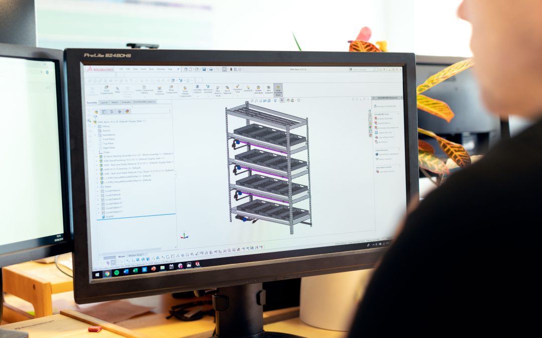
CAD file formats are not interchangeable. STEP is usually best for sharing 3D manufacturing geometry, native files such as SLDPRT preserve edit history, STL is mainly for mesh-based 3D Štampa, DXF supports 2D cutting profiles, DWG supports drawings, and IGES is often used for surface exchange. Choosing the wrong format can cause lost features, poor quotes, or unusable production files.
This post covers the practical checks, documentation decisions, and engineering tradeoffs behind CAD file formats. If you are preparing a quote request, production release, or supplier package, the details below help reduce rework before the project reaches the shop floor.
Why file format choice matters
A supplier can only quote and manufacture what the file communicates. A mesh file may show shape but not design intent. A neutral solid file may preserve geometry but not feature history. A drawing file may define dimensions but not provide machinable 3D geometry.
The safest approach is to send a package: native CAD if available, STEP for 3D geometry exchange, PDF drawings for human review, and process-specific files such as DXF for laser cutting or STL for additive manufacturing.
Match the format to the next action
If the next step is CNC mašinska obrada, STEP plus a toleranced PDF drawing is usually more useful than STL. If the next step is sheet metal laser cutting, DXF geometry plus thickness and material notes are essential. If the next step is design revision, the native CAD file helps preserve editable features.
File conversion should be checked before production because exported geometry can lose units, surface quality, assembly constraints, or hidden design information.
CAD file format guide
| Format | Best use | Main caution |
| STEP / STP | 3D solid exchange for manufacturing and supplier quoting | Does not always preserve native feature history |
| IGES / IGS | Surface exchange and legacy CAD workflows | Can create surface gaps or repair work |
| STL | 3D printing and mesh workflows | Poor choice for editable production CAD |
| DXF | 2D profiles for cutting, routing, waterjet, laser, and sheet metal | Needs material, thickness, and bend notes separately |
| DWG | 2D drawing and drafting exchange | Not enough by itself for 3D manufacturing |
| SLDPRT / native CAD | Editable design work and revision control | May require the same CAD platform or version |
Engineering examples
Laser-cut bracket: The supplier needs a clean DXF profile, material thickness, bend information if formed, and a PDF drawing. A screenshot or STL is not enough.
Machined housing: The machinist can program from STEP geometry, but the drawing must still define datums, tolerances, threads, surface finish, and inspection requirements.
Related X-PROCAD support: CAD services, CNC mašinska obrada, injection molding, 3D Štampa, and contact X-PRO CAD.
Najčešća pitanja
What CAD file format is best for manufacturing?
STEP is commonly used for 3D manufacturing exchange, but it should be paired with drawings and process-specific notes.
Is STL a CAD file?
STL is a mesh format. It is useful for many 3D printing workflows but is usually not ideal for editable production CAD.
Should I send native CAD files to a supplier?
Send native files when editability matters, but also provide neutral formats and PDFs so suppliers can access the geometry and requirements.
Upload your part, drawing, or sketch for a manufacturability review. X-PROCAD can help clean, convert, and prepare CAD files for supplier-ready manufacturing. Contact X-PRO CAD to confirm the right path for your project.












Скорашњи коментари