
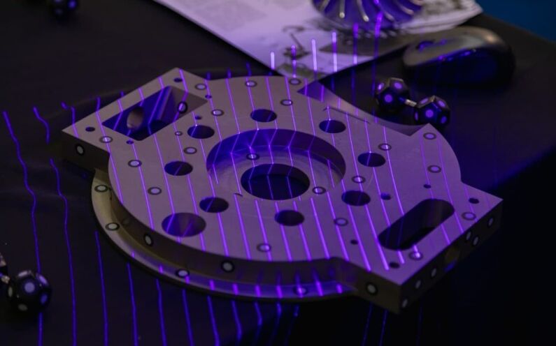
To reverse engineer an obsolete part, start by documenting the sample, identifying critical interfaces, measuring or scanning the geometry, rebuilding clean CAD, assigning tolerances, and creating supplier-ready drawings. The goal is not to copy damage or wear; it is to recreate the design intent so the replacement fits, functions, and can be manufactured consistently. The best results come from combining physical measurement with engineering judgment.
This post covers the practical checks, documentation decisions, and engineering tradeoffs behind reverse engineer obsolete parts. If you are preparing a quote request, production release, or supplier package, the details below help reduce rework before the project reaches the shop floor.
Start with function, not geometry
Obsolete parts often arrive without drawings, part history, or material records. Before modeling, define what the part actually does. Does it locate another component, transmit torque, seal pressure, hold alignment, or protect electronics? Function tells the engineer which dimensions are critical and which surfaces can be simplified.
A discontinued bracket may look simple until the hole pattern controls motor alignment. A spacer may look like a turned cylinder until thermal expansion, material hardness, or finish affects its performance.
Rebuild the design intent
A worn sample can mislead a project if every scratch, deformation, and ovalized hole is copied into CAD. Reverse engineering should separate original design intent from years of use. Critical diameters, thread sizes, flatness, perpendicularity, and mating surfaces should be reconstructed around practical manufacturing tolerances.
Once the model is complete, create the manufacturing file set: native CAD where available, neutral STEP, 2D drawing, material notes, finish requirements, and inspection dimensions.
Obsolete part reverse engineering checklist
| Step | What to capture | Reason it matters |
| Document the part | Photos, markings, condition, assembly context | Preserves evidence before teardown or measurement |
| Identify interfaces | Mounting holes, bores, seals, threads, mating faces | Controls fit and function |
| Measure geometry | Scan data plus calipers, micrometers, CMM, gauges as needed | Reduces risk of copying worn features |
| Rebuild CAD | Parametric features and idealized surfaces | Creates editable manufacturing geometry |
| Define tolerances | GD&T, fits, surface finish, inspection dimensions | Prevents supplier interpretation errors |
| Validate before production | Assembly fit, supplier review, first article inspection | Catches mistakes before batch production |
Engineering examples
Damaged machine guard hinge: A hinge leaf from an old machine is bent and no longer sits flat. The reverse engineered model should restore the flat reference surface, preserve hole spacing, and call out material thickness rather than copying the bent condition.
Discontinued marine spacer: A spacer with corrosion damage needs replacement. Measurement confirms the bore and face-to-face length, while the drawing adds material and finish notes appropriate for the operating environment.
Related X-PROCAD support: Reverse engineering, CAD services, government engineering support, and contact X-PRO CAD.
FAQ
Can a damaged part be reverse engineered?
Yes. Damage can be documented and corrected during CAD reconstruction when the functional design intent is understood.
What if I only have one sample?
One sample is often enough to begin, but assembly context, photos, and functional requirements help identify worn or uncertain features.
Should obsolete parts be copied exactly?
Not always. Critical geometry should be preserved, but wear, deformation, and avoidable manufacturing problems should be corrected.
Upload your part, drawing, or sketch for a manufacturability review. X-PROCAD can help recreate obsolete components as clean CAD, drawings, and production-ready documentation. Contact X-PRO CAD to confirm the right path for your project.


Recent Comments