Nearly one-third of automation systems do not perform as expected — often because of incomplete scoping and insufficient de-risking during design and validation phases, not because the robots themselves are faulty.
Automation projects rarely fail because of robotics.
They fail because the product was never engineered for automation in the first place.
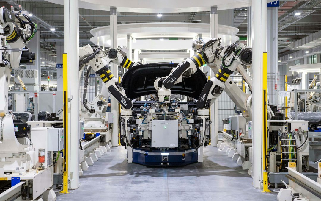
Manufacturers invest in automated assembly systems, robotic handling, and integrated production lines expecting higher throughput, improved repeatability, and reduced labor dependency. Capital is allocated, timelines are set, and performance targets are defined around cycle time, yield, and cost per unit.
Then reality intervenes.
Tolerance conflicts cause misalignment at high speed. Parts do not feed consistently. Grippers struggle with geometry that was acceptable in manual assembly. Fastening strategies require redesign. Sensors misread surfaces that were never specified for automated inspection. Cycle times fluctuate. Scrap increases. Debugging stretches far beyond initial projections.
At that stage, the robotics are rarely the primary issue. The system is performing exactly as designed. The problem is that the product was not.
In most cases, the root cause is upstream. It begins in design decisions made long before automation was considered a constraint.
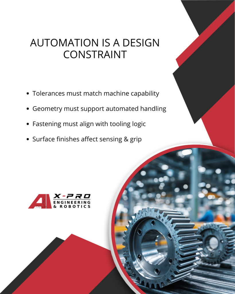
Automation Is a Design Constraint, Not a Retrofit Feature
Automation changes how a product must be engineered.
A part that works in manual assembly does not automatically work in an automated cell. Human operators compensate for variation. They adjust grip force, reorient components, correct minor misfits, and make judgment calls in real time. Machines operate within defined parameters. When variation exceeds those limits, the process fails.
Designing for automation requires acknowledging that automated systems remove flexibility from the equation. Variability that is acceptable in manual assembly becomes unacceptable at scale.
When design teams fail to account for automation early, predictable problems emerge:
- Inconsistent tolerances that cause robotic misalignment
- Geometry that prevents reliable part feeding or orientation
- Fastening strategies incompatible with automated tooling
- Surface finishes that interfere with gripping or optical sensing
- Stack-up errors that compound across high-speed assembly
These are not robotics failures. They are design oversights.
Tolerance Strategy Must Reflect Machine Reality
Automation amplifies tolerance interaction.
In manual processes, small deviations may go unnoticed. In automated systems, even minor dimensional drift can cause:
- Pick-and-place inaccuracies
- Binding during insertion
- Sensor misreads
- Increased scrap rates
- Line stoppages
Tolerance stack-ups must be modeled intentionally. Critical interfaces should be defined based on the actual capability of machining processes and automation equipment, not arbitrary specification.
Geometry Must Support Handling and Orientation
Automated assembly depends on repeatable part presentation.
If parts lack defined gripping surfaces, orientation features, or consistent center-of-mass balance, feeding systems become unreliable. Vibratory bowls, conveyors, and robotic grippers require predictable interaction points.
Automation-ready geometry often includes:
- Flat or controlled gripping surfaces
- Chamfers or lead-ins for alignment
- Symmetry or clearly defined orientation features
- Features that reduce ambiguity during positioning
Ignoring these considerations shifts complexity to automation integrators and increases downstream cost.
Assembly Logic Must Be Engineered, Not Assumed
Automated systems execute a defined sequence. They do not improvise.
Designers must consider:
- Tool access and clearance
- Fastener accessibility for automated drivers
- Order of operations to prevent obstruction
- Interference between mechanical and electrical components
When assembly sequencing is not validated during CAD development, redesign becomes inevitable during automation integration.
| Design Area | What Happens in Manual Assembly | What Happens in Automation | Required Engineering Discipline |
|---|---|---|---|
| Tolerance Strategy | Operators compensate for small dimensional variation | Minor drift causes pick-and-place inaccuracies, binding, sensor misreads, scrap, and line stoppages | Model tolerance stack-ups intentionally and align critical interfaces with actual machine capability |
| Part Geometry | Humans reorient parts and adjust grip dynamically | Unreliable feeding, unstable orientation, inconsistent gripping | Design flat or controlled gripping surfaces, chamfers, symmetry, and defined orientation features |
| Assembly Logic | Operators adapt sequence and work around obstructions | Sequence conflicts, fastening misalignment, mechanical-electrical interference | Validate tool access, fastening strategy, sequencing, and component coordination during CAD development |
Surface and Material Decisions Matter
Automation relies on consistent interaction between materials and machines.
Surface treatments, coatings, and finishes influence:
- Friction during feeding
- Reliability of vision systems
- Gripper stability
- Static buildup and contamination risk
Material choices must reflect not only functional performance but also automation compatibility.
Design for automation means treating automated manufacturing as a primary constraint during engineering and CAD modeling. It is not an add-on after product geometry is finalized.
Automation success is determined long before equipment is installed.facturing as a primary constraint during CAD modeling and engineering, not as a downstream integration step.
Why Most Manufacturing Automation Fails Before Production
Automation exposes variability. It does not absorb it.
Manual assembly can hide poor tolerance control, ambiguous drawings, or loosely defined fits. Operators compensate. They adjust parts, apply force, and correct inconsistencies in real time.
Automated systems do not adapt. They execute within defined mechanical and dimensional limits. When variation exceeds those limits, failure rates increase immediately.
Most automation failures are not equipment failures. They are upstream engineering failures.
1. Poor Tolerance Strategy
Tolerance planning is often treated as a documentation exercise rather than a systems decision.
In automation, tolerance interaction directly impacts:
- Robotic pick accuracy
- Insertion force consistency
- Alignment during high-speed assembly
- Inspection repeatability
- Yield stability at scale
Common design mistakes include:
- Arbitrary tolerance selection without stack-up analysis
- Over-constraining non-critical dimensions
- Ignoring cumulative variation across assemblies
- Failing to align tolerances with machining capability
Overly tight tolerances increase cost and machining time. Overly loose tolerances introduce unpredictability. Automation requires controlled, intentional tolerance architecture aligned with actual process capability and equipment precision.
2. Geometry Not Optimized for Handling
Geometry designed for aesthetics or manual assembly often behaves unpredictably in automated systems.
Automated cells depend on repeatable interaction between part and machine. When geometry lacks clear handling logic, the system becomes unstable.
Typical issues include:
- No defined gripping surfaces
- Asymmetrical forms without orientation control
- Center-of-mass imbalance affecting pick reliability
- Sharp transitions that interfere with insertion
Automation-ready geometry prioritizes:
- Stable, repeatable gripping zones
- Lead-ins and chamfers for guided insertion
- Clear orientation features
- Reduced ambiguity during positioning
When geometry ignores automation constraints, complexity shifts to integrators. That complexity becomes cost.
3. Assembly Logic Ignored During Design
Automated systems execute a predefined sequence. They do not improvise or reorder tasks.
If assembly logic is not engineered during CAD development, integration friction is inevitable.
Frequent failure points include:
- Tool access blocked by adjacent components
- Fastener placement incompatible with automated drivers
- Sequence conflicts requiring part redesign
- Interference between subassemblies
Designers must validate:
- Order of operations
- Tool clearance envelopes
- Fastening strategy alignment
- Accessibility for automated equipment
Assembly logic must be treated as an engineering constraint, not a production detail.
4. Electrical and Mechanical Misalignment
Automation environments require tight coordination between mechanical structures, sensors, actuators, and wiring.
When electrical and mechanical domains are developed in isolation, integration issues surface late.
Examples include:
- Sensor fields obstructed by mechanical components
- Cable routing conflicts
- Insufficient clearance for motion
- Interference between moving assemblies and wiring
These failures rarely originate on the production floor. They originate in fragmented design workflows.
Cross-functional coordination must occur before automation design is finalized.
Automation failure is usually a systems design problem.
When tolerance control, geometry, assembly logic, and cross-disciplinary coordination are engineered early, automation performs as expected.
When they are not, the line simply reveals what design overlooked.
Automation-Ready Product Design
Automation-ready product design is not a feature added at the end of development. It is a structured engineering approach applied from the first CAD model.
When automation is treated as a primary constraint, design decisions become more intentional. Geometry, tolerances, materials, and assembly logic are evaluated not only for functionality, but for repeatability at production speed.
Designing for automation requires disciplined coordination across CAD, mechanical engineering, and manufacturing planning.
Key principles include:
- CAD models built with manufacturing constraints defined early
Critical dimensions, datum structures, and interface relationships must reflect real machining and automation capability, not theoretical intent. - Tolerance stack-ups validated before tooling investment
Variation must be modeled across assemblies to prevent downstream insertion failures, misalignment, and sensor errors. - Fastening methods aligned with automated equipment
Screw orientation, access clearance, torque strategy, and sequencing must match the capabilities of automated drivers and tooling systems. - Materials selected with gripping, sensing, and repeatability in mind
Surface texture, coatings, and friction characteristics directly influence feeding reliability and vision system accuracy. - Assembly sequences modeled before production line design
Order of operations, interference zones, and tool paths should be validated digitally before capital is committed to automation hardware.
When these elements are engineered early, automation becomes a confirmation of design discipline rather than a stress test of unresolved issues.
Automation should validate engineering decisions, not expose their weaknesses.
| Design Dimension | Conventional Product Design | Automation-Ready Product Design |
|---|
| Tolerance Planning | Defined per part, often isolated | Modeled across assemblies with stack-up validation |
| Geometry | Optimized for function and aesthetics | Optimized for handling, orientation, and repeatability |
| Fastening | Chosen for accessibility and cost | Aligned with automated tooling capability and sequencing |
| Materials & Surfaces | Selected for strength and appearance | Evaluated for grip reliability, sensing, and consistency |
| Assembly Strategy | Sequencing addressed during production planning | Sequencing validated during CAD and engineering development |
The Financial Risk of Ignoring Automation Constraints
Automation investments are capital-intensive. Once equipment is specified, programmed, and installed, flexibility decreases significantly. Production lines are engineered around defined geometry, cycle time assumptions, and tolerance expectations. Changing those assumptions late is expensive.
When products require modification after automation equipment is in place, the impact extends beyond simple redesign.
Consequences often include:
- Delayed launch timelines as engineering changes ripple through tooling, programming, and validation
- Increased tooling modification costs to adjust fixtures, grippers, or automated drivers
- Reduced throughput when cycle times must be slowed to accommodate variability
- Compromised quality control due to inconsistent alignment or insertion forces
- Higher long-term operational expense from ongoing adjustments, scrap, and maintenance
In many cases, the automation system itself is functioning correctly. The misalignment exists between the product design and the system it must operate within.
Engineering discipline upstream protects capital downstream. When automation constraints are integrated into design from the beginning, capital investments support scalability rather than expose avoidable weaknesses.
Conclusion: Automation Success Is Determined in Design, Not on the Line
Manufacturing automation does not fail because robotics lack capability. It fails when products are not engineered for repeatability, tolerance control, and integration from the beginning.
Robotic systems, automated assembly cells, and smart production lines execute with precision. They expose dimensional drift, poor sequencing logic, and fragmented coordination. When automation struggles, it is often revealing weaknesses that were embedded upstream during design.
Companies that implement automation successfully treat it as an engineering constraint, not a retrofit enhancement. They validate tolerance stack-ups before tooling is purchased. They align geometry with handling logic. They coordinate mechanical and electrical systems early. They model assembly sequencing before capital is committed to production hardware.
This approach protects timelines, stabilizes throughput, and preserves investment.
At X-PRO, we support manufacturers and product teams that require production-ready engineering from concept through manufacturing. Our capabilities span CAD services, mechanical engineering, prototyping, and manufacturing execution. We help organizations reduce automation risk by ensuring designs are structured for repeatability, manufacturability, and integration from the start.
If you are evaluating an automation initiative or preparing a product for automated production, contact us at project.inquiries@x-professionals.com or call (571) 583-3710 to discuss your requirements and determine the most practical path to execution.ducts are engineered for repeatability, manufacturability, and automation readiness before they reach the line.

Recent Comments