According to a recent analysis of automation projects, about 73 % of automation initiatives fail because organizations attempt to automate broken processes instead of addressing underlying process issues first — not because of the technology itself.
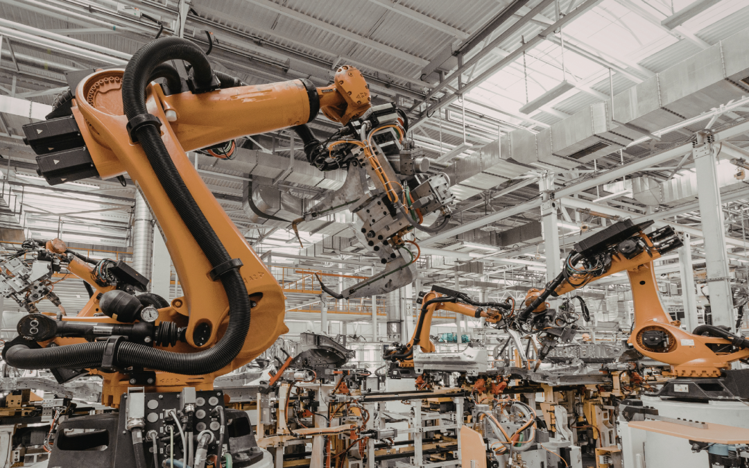
Automation projects rarely fail because of robotics hardware or controls logic. They fail because dimensional instability was embedded into the product and process long before automation was introduced.
When automated systems begin to struggle, the diagnosis is predictable. Teams look at programming. They question sensors. They adjust end effectors. They analyze cycle times. They revisit the integrator’s work. The assumption is that something within the automation layer is underperforming.
In most cases, it is not.
Robotic systems execute exactly what they are given. They follow fixed paths, defined coordinates, and repeatable force profiles without deviation. When they miss pick positions, misalign fasteners, or generate inconsistent inspection results, they are often revealing upstream design weaknesses that manual assembly previously masked. Human operators compensate for variation. Robots do not.
Automation does not create precision problems. It exposes them. At scale and at speed, unmanaged tolerance stack-ups, poor datum strategy, fixture instability, and incomplete mechanical-electrical coordination become visible. What appeared acceptable in low-volume or manual production becomes unstable under repeatable, automated execution.
Automation is not primarily a robotics problem. It is a tolerance management problem engineered long before the first robot is commissioned.
Automation is not primarily a robotics problem. It is a tolerance management problem.
Why Manual Processes Hide Dimensional Instability
Human Compensation Masks Variation
Manual assembly environments are inherently adaptive. Skilled operators continuously compensate for variation without formally measuring or documenting it. What appears stable at the process level is often being stabilized by human intervention.
Manual assembly can tolerate:
- Minor misalignments between mating components
- Slight dimensional variation between batches
- Surface inconsistencies affecting contact or sensing
- Real-time force adjustments during insertion or fastening
- Sequencing irregularities in multi-step assembly
An operator will rotate a part slightly to align it. Apply additional pressure during a press-fit. Adjust angle before fastening. Re-seat a component if it does not feel correct. These micro-corrections happen instinctively.
This adaptive behavior hides upstream dimensional instability. Variation exists, but it is absorbed by human flexibility.
At low volume or moderate throughput, this compensation can make a marginal design appear robust.
Automation Removes the Buffer
Automated systems eliminate that buffer.
Robotic systems execute:
- Fixed motion paths
- Defined spatial coordinates
- Repeatable force and torque profiles
- Pre-programmed sequencing logic
They do not “feel” resistance. They do not adjust angles mid-operation. They do not reinterpret misalignment as a cue to reposition.
If a hole location drifts by fractions of a millimeter beyond the tolerance envelope, the robot does not compensate. If part geometry varies slightly between suppliers, the gripper does not adapt. If thermal expansion shifts a fixture, the system continues executing the same coordinates.
Automation assumes dimensional discipline. It does not correct for its absence.
Repeatability Amplifies Instability
Under automation, variability compounds rather than hides.
At higher cycle speeds and repetition volumes:
- Tolerance stack-ups accumulate across assemblies
- Misalignments generate consistent failure modes
- Wear effects amplify dimensional drift
- Inspection systems flag inconsistencies that humans would ignore
A process that appeared stable during manual validation can deteriorate rapidly once exposed to automated repeatability requirements.
What worked manually at low volume often collapses under automated execution. The difference is not robotics capability. The difference is tolerance control.
Where Tolerance Breakdowns Actually Occur
Tolerance instability rarely originates from a single dimension. It emerges from structural design decisions made upstream. When automation fails, the root cause can usually be traced to one of several predictable failure zones.
Cumulative Tolerance Stack-Ups
In multi-part assemblies, variation accumulates. Without full tolerance stack analysis, small dimensional deviations compound into functional misalignment.
Common upstream issues include:
- Multi-part assemblies released without comprehensive stack analysis
- Linear dimensioning instead of functional datum-based structures
- Worst-case scenarios not evaluated against real automation constraints
When automation is introduced, the impact becomes immediate:
- Gripper misalignment during pick-and-place operations
- Fastener cross-threading due to axis offset
- Inconsistent press-fit results across production batches
Manual assembly can absorb marginal stack variation. Automated systems cannot. At cycle speed, even minor positional drift becomes a repeatable defect.
Fixture and Workholding Repeatability
Fixtures are often assumed to be stable reference structures. In reality, they are dynamic components subject to load, wear, and thermal influence.
Breakdowns commonly stem from:
- Insufficient fixture rigidity under repetitive loading
- Thermal expansion not modeled into the system tolerance envelope
- Tool wear excluded from positional tolerance assumptions
The operational consequences include:
- Position drift during high-speed operation
- Inconsistent inspection measurements
- Elevated false reject rates in automated quality control
A fixture that shifts by fractions of a millimeter can destabilize an entire automated cell. Without repeatable reference geometry, robotic precision becomes irrelevant.
| Failure Zone | Upstream Design Issue | Automation Impact |
|---|---|---|
| Cumulative Tolerance Stack-Ups | No full stack analysis, poor datum structure, ignored worst-case scenarios | Gripper misalignment, cross-threading, inconsistent press-fits |
| Fixture and Workholding Repeatability | Insufficient rigidity, unmodeled thermal expansion, ignored tool wear | Position drift, inspection variability, false rejects |
| Geometry Designed for Human Access | Manual-focused clearances, adaptive fastening logic, non-specified sensing surfaces | Sensor misreads, feeding instability, collision risk |
| Mechanical and Electrical Misalignment | Late coordination, undefined surface specs, motion-envelope conflicts | Integration delays, commissioning rework, extended ramp-up |
Geometry Designed for Human Access, Not Automation
Many products are originally designed around manual assembly. Clearances, access points, and fastening logic assume human dexterity.
Typical design characteristics include:
- Clearances optimized for hands rather than tooling
- Fastening strategies that require angular adjustment during insertion
- Surfaces not specified for automated optical or proximity sensing
When transferred to automation, these design decisions generate:
- Sensor misreads caused by inconsistent surface reflection or finish
- Feeding inconsistencies in vibratory or robotic systems
- Increased collision risk due to insufficient motion envelope clearance
Automation requires geometry engineered around predictable mechanical motion, not adaptive human correction.
Mechanical and Electrical Misalignment
Automation is inherently multidisciplinary. When mechanical and electrical domains are coordinated late, dimensional and sensing conflicts emerge during integration.
Frequent structural errors include:
- Late-stage coordination between mechanical and controls teams
- Sensor selection without explicit surface and material specification
- Cable routing that interferes with motion envelopes or service access
The downstream effects are costly:
- Integration delays during commissioning
- Mechanical rework to accommodate electrical constraints
- Extended ramp-up periods before stable throughput is achieved
Automation breakdown is often a coordination failure disguised as a programming problem.
Structural Mistakes That Precede Automation Failure
Automation breakdown rarely begins on the production floor. It begins in the sequence of decisions made before automation is formally introduced. By the time integration starts, the structural weaknesses are already embedded.
One of the most common errors is introducing automation after product geometry is frozen. When handling logic, fastening strategy, and sensing requirements are forced onto a fixed design, compromises become inevitable. Clearances are insufficient. Datum strategies are misaligned. Critical dimensions were never defined in relation to robotic motion.
Another frequent failure point is skipping tolerance simulation prior to tooling investment. Without worst-case or statistical stack-up validation, variation is only discovered during commissioning. At that stage, fixture redesign and component modification are significantly more expensive.
Prototype validation is often performed manually rather than under automation constraints. A prototype that assembles successfully by hand does not prove it can withstand high-speed, repeatable robotic execution. Manual validation hides instability that automation later exposes.
Lack of disciplined GD&T aligned with functional requirements further compounds the issue. When tolerances are assigned without reference to real mating conditions, assembly sequence, and automation repeatability thresholds, dimensional control becomes theoretical rather than operational.
Finally, integration is frequently treated as a commissioning phase rather than a design phase. Mechanical, electrical, controls, and manufacturing considerations are sequenced instead of coordinated. By the time conflicts surface, redesign replaces optimization.
The pattern is consistent. Automation failure is not a robotics problem. It is the result of upstream engineering decisions that did not treat repeatability as a core design constraint from the beginning.
Automation failure is usually embedded before capital is deployed.
What Design-for-Automation Actually Requires
Correcting automation instability is not about refining robot code. It requires structural changes in how products and systems are engineered from the beginning. Design-for-automation is a discipline, not a retrofit exercise.
Treat Automation as a Design Constraint
Automation must influence the product architecture early. It cannot be layered onto a geometry that was finalized without regard to handling, sensing, or repeatability.
Automation requirements should directly shape:
- Geometry and access strategy
- Datum structure and tolerance hierarchy
- Fastening methods and alignment logic
- Handling features for gripping and positioning
When these elements are engineered with automation in mind, robotic execution becomes stable. When they are added later, compromise and variability follow.
Automation is not an enhancement phase. It is a design constraint.
Validate Tolerance Stack-Ups Before Hardware Procurement
Before tooling is commissioned or capital equipment is purchased, dimensional behavior must be modeled under real operating assumptions.
This includes:
- Worst-case tolerance analysis
- Statistical tolerance modeling for volume production
- Functional mapping of critical dimensions tied to assembly sequence
Upfront validation protects:
- Throughput stability
- Scrap and rework rates
- Tooling and fixture investment
Discovering tolerance conflicts after hardware procurement shifts correction from engineering optimization to cost containment.
Align Mechanical and Electrical Early
Automation systems are multidisciplinary by nature. Mechanical geometry, sensing strategy, and motion logic cannot be sequenced independently.
Effective coordination requires parallel development across:
- Mechanical engineering
- Controls architecture
- Sensor specification and placement
- Motion planning and collision envelopes
Early alignment reduces:
- Integration conflicts
- Commissioning delays
- Redesign during ramp-up
When disciplines converge only during commissioning, instability is already embedded.
Prototype Under Real Automation Conditions
Manual assembly validation does not replicate automated behavior. A prototype that works in a lab environment may fail under repetitive, high-speed execution.
Validation should simulate:
- Actual cycle speed
- Repetition volume and cumulative load
- Thermal expansion effects
- Wear and degradation over time
Automation reliability is proven under repetition, not demonstration.
| Design-for-Automation Requirement | Engineering Action | Operational Protection |
|---|
| Automation as Design Constraint | Integrate handling, datum, and fastening logic into early geometry decisions | Stable robotic execution and predictable integration |
| Pre-Tooling Tolerance Validation | Perform worst-case and statistical stack analysis tied to functional requirements | Reduced scrap, protected tooling investment, consistent throughput |
| Early Mechanical-Electrical Alignment | Develop geometry, sensing, and motion logic in parallel | Fewer integration conflicts and shorter commissioning cycles |
| Automation-Level Prototyping | Validate under real cycle speeds, thermal conditions, and repetition volume | Reliable ramp-up and reduced post-launch rework |
The Financial Reality of Getting It Wrong
When tolerance discipline is neglected upstream, the financial consequences surface quickly and compound over time.
Capital equipment can sit idle while integration issues are diagnosed. Commissioning windows extend beyond schedule. Engineering teams are redirected from forward development to corrective rework. Tooling must be modified or replaced. Fixtures are redesigned. Cycle times are reduced to stabilize instability that should not exist.
The downstream effects include:
- Capital equipment underutilization
- Integration rework and extended commissioning
- Tool redesign and secondary machining costs
- Delayed product launch and missed revenue windows
- Increased scrap rates and quality variability
- Margin erosion across the production lifecycle
Automation investments are typically justified by throughput, repeatability, and cost efficiency. When upstream dimensional instability disrupts those assumptions, the return on investment deteriorates.
The cost of engineering tolerance discipline early is marginal compared to the cost of correcting instability after automation is deployed.
The cost of upstream tolerance discipline is negligible compared to post-automation correction.
Conclusion: Automation Failure Is Engineered Upstream
Automation does not fail because robots are inaccurate. It fails when dimensional instability, unmanaged tolerance stack-ups, and fragmented coordination are built into the system before automation is introduced.
Robotic systems execute with consistency. They expose weak datum strategies, incomplete stack analysis, and geometry that was never engineered for repeatable handling. When instability appears on the line, the root cause is almost always embedded in design.
Organizations that scale automation successfully treat repeatability as a core engineering constraint. They validate tolerances before tooling is commissioned. They align mechanical and electrical disciplines early. They prototype under real automation conditions. They structure products for precision before capital is deployed.
At X-PRO, we support manufacturers and product teams that require production-ready engineering from concept through manufacturing. Our capabilities span CAD services, mechanical engineering, prototyping, and manufacturing execution. We help organizations reduce automation risk by ensuring designs are structured for repeatability, manufacturability, and integration from the start.
If you are planning an automation initiative or preparing a product for automated production, contact us at project.inquiries@x-professionals.com or call (571) 583-3710 to discuss your requirements and determine the most practical path to execution.
Frequently Asked Questions
Is automation failure usually caused by robotics hardware?
In most cases, no. Modern robotic systems are highly precise and repeatable. Failures more commonly originate from unmanaged tolerance stack-ups, weak datum structures, fixture instability, or incomplete coordination between mechanical and electrical systems. Automation exposes instability that was already present.
Why does manual assembly succeed when automation fails?
Human operators subconsciously compensate for variation. They adjust alignment, apply variable force, and correct minor misfits in real time. Robots execute fixed paths and force profiles. They do not adapt to dimensional drift, which makes upstream instability visible under automated conditions.
What is tolerance stack-up and why does it matter in automation?
Tolerance stack-up refers to the cumulative effect of dimensional variation across multiple components in an assembly. In automated systems, even small deviations can shift part position outside the allowable window for gripping, fastening, or inspection. Without proper stack analysis, these compounded variations create repeatable failure modes.
When should automation considerations be introduced in product development?
Automation constraints should be introduced during early design stages, before geometry is frozen and before tooling investment. Handling logic, datum strategy, fastening approach, and sensing requirements must influence the design architecture from the beginning. Retrofitting automation after design completion significantly increases integration risk.
How can companies reduce automation risk before deployment?
Risk reduction requires structured engineering discipline:
- Perform worst-case and statistical tolerance analysis
- Align mechanical and electrical systems in parallel
- Validate prototypes under real automation cycle conditions
- Treat repeatability as a primary design requirement
Upstream precision and coordination are the most effective ways to protect throughput, reduce scrap, and stabilize automation performance.

Recent Comments