
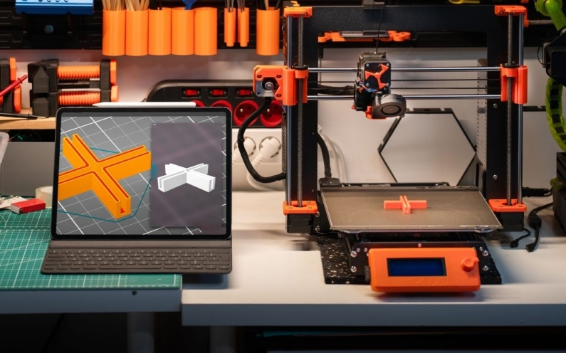
A DFM checklist helps confirm that a CAD model can be manufactured reliably before money is spent on prototypes, tooling, or supplier quotes. Check manufacturing process, material, tolerances, wall thickness, tool access, draft, fasteners, assembly sequence, drawing notes, and inspection requirements. The best time to run DFM is before the design is released, because late corrections cost more and delay production.
This post covers the practical checks, documentation decisions, and engineering tradeoffs behind DFM checklist. If you are preparing a quote request, production release, or supplier package, the details below help reduce rework before the project reaches the shop floor.
DFM starts with the manufacturing process
A model that looks finished may still be impossible or expensive to build. CNC machining, injection molding, sheet metal, casting, additive manufacturing, and fabrication all impose different rules. Geometry is never neutral; it either supports the chosen process or fights it.
For example, a pocket with sharp internal corners may look fine in CAD but requires small tools, extra machining time, or EDM. A plastic enclosure with no draft may function in a prototype but create tooling and ejection problems in molding.
What to review before supplier release
Before sending files to suppliers, validate the model, drawing, and intended production method together. Make sure tolerances match actual functional needs, not arbitrary precision. Check that the drawing explains what the CAD model cannot: material, finish, critical dimensions, inspection notes, and revision status.
A clean DFM review reduces quoting confusion, revision cycles, and expensive redesign after the first prototype.
DFM checklist for CAD release
| DFM area | What to check | Common failure avoided |
| Process fit | Is the design suited to CNC, molding, sheet metal, casting, or printing? | Choosing an expensive or impractical process |
| Material | Does the material match loads, environment, finish, and availability? | Strength, heat, corrosion, or supply issues |
| Tolerances | Are tight tolerances limited to functional features? | Unnecessary cost and inspection difficulty |
| Tool access | Can tools reach pockets, corners, and holes? | Redesign after CAM or supplier review |
| Draft and wall thickness | Are molded features designed for flow, cooling, and ejection? | Warp, sink marks, and tool changes |
| Drawing package | Are notes, datums, finish, and revisions clear? | Supplier assumptions and quote mismatches |
Engineering examples
Machined mounting plate: A plate has twelve holes. Only four locate the assembly; the rest are clearance holes. DFM reduces cost by tightly tolerancing the locating holes and relaxing noncritical clearance features.
Plastic sensor enclosure: The prototype works as a 3D print, but the molded version needs draft, uniform walls, ribs instead of thick sections, and boss design that avoids sink marks.
Related X-PROCAD support: CAD services, prototyping and manufacturing, CNC machining, injection molding, and contact X-PRO CAD.
FAQ
When should a DFM review happen?
A DFM review should happen before prototype release, supplier quoting, tooling, or production so design changes are still inexpensive.
What is the most common DFM mistake?
One common mistake is applying tight tolerances everywhere instead of only where the function requires them.
Does DFM replace engineering drawings?
No. DFM improves the design, while drawings communicate the approved requirements for manufacturing and inspection.
Upload your part, drawing, or sketch for a manufacturability review. X-PROCAD can help identify DFM risks before your files reach suppliers or tooling. Contact X-PRO CAD to confirm the right path for your project.









Recent Comments